| 10 |
INT |
R |
|
|
Gateway device name, characters 1-2 (2 ASCII chars, big-endian) |
| 11 |
INT |
R |
|
|
Gateway device name, characters 3-4 (2 ASCII chars, big-endian) |
| 12 |
INT |
R |
|
|
Gateway device name, characters 5-6 (2 ASCII chars, big-endian) |
| 13 |
INT |
R |
|
|
Gateway device name, characters 7-8 (2 ASCII chars, big-endian) |
| 14 |
INT |
R |
|
|
Gateway device name, characters 9-10 (2 ASCII chars, big-endian) |
| 15 |
INT |
R |
|
|
Gateway device name, characters 11-12 (2 ASCII chars, big-endian) |
| 16 |
INT |
R |
|
|
Gateway device name, characters 13-14 (2 ASCII chars, big-endian) |
| 17 |
INT |
R |
|
|
Gateway device name, characters 15-16 (2 ASCII chars, big-endian) |
| 18 |
INT |
R |
|
|
Gateway device name, characters 17-18 (2 ASCII chars, big-endian) |
| 19 |
INT |
R |
|
|
Gateway device name, characters 19-20 (2 ASCII chars, big-endian) |
| 30 |
INT |
R |
|
|
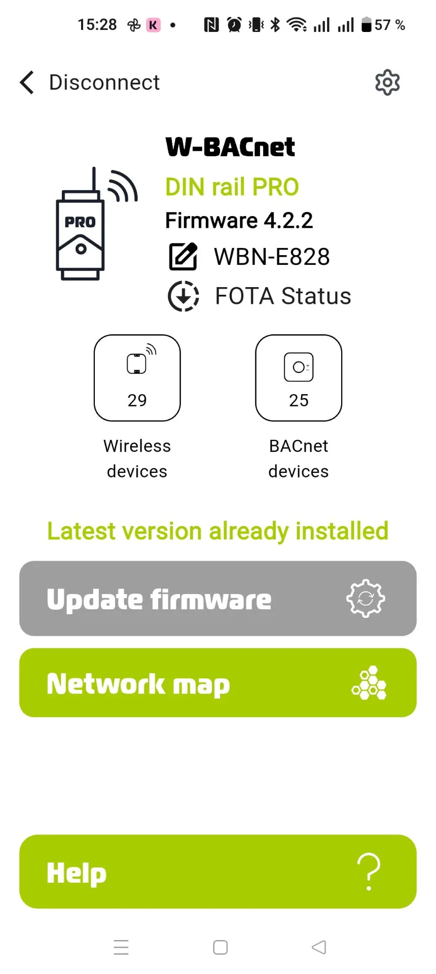
Number of wireless nodes in the mesh network |
| 31 |
INT |
R |
|
|
Number of modbus server/slave devices |
| 32 |
INT |
R |
|
|
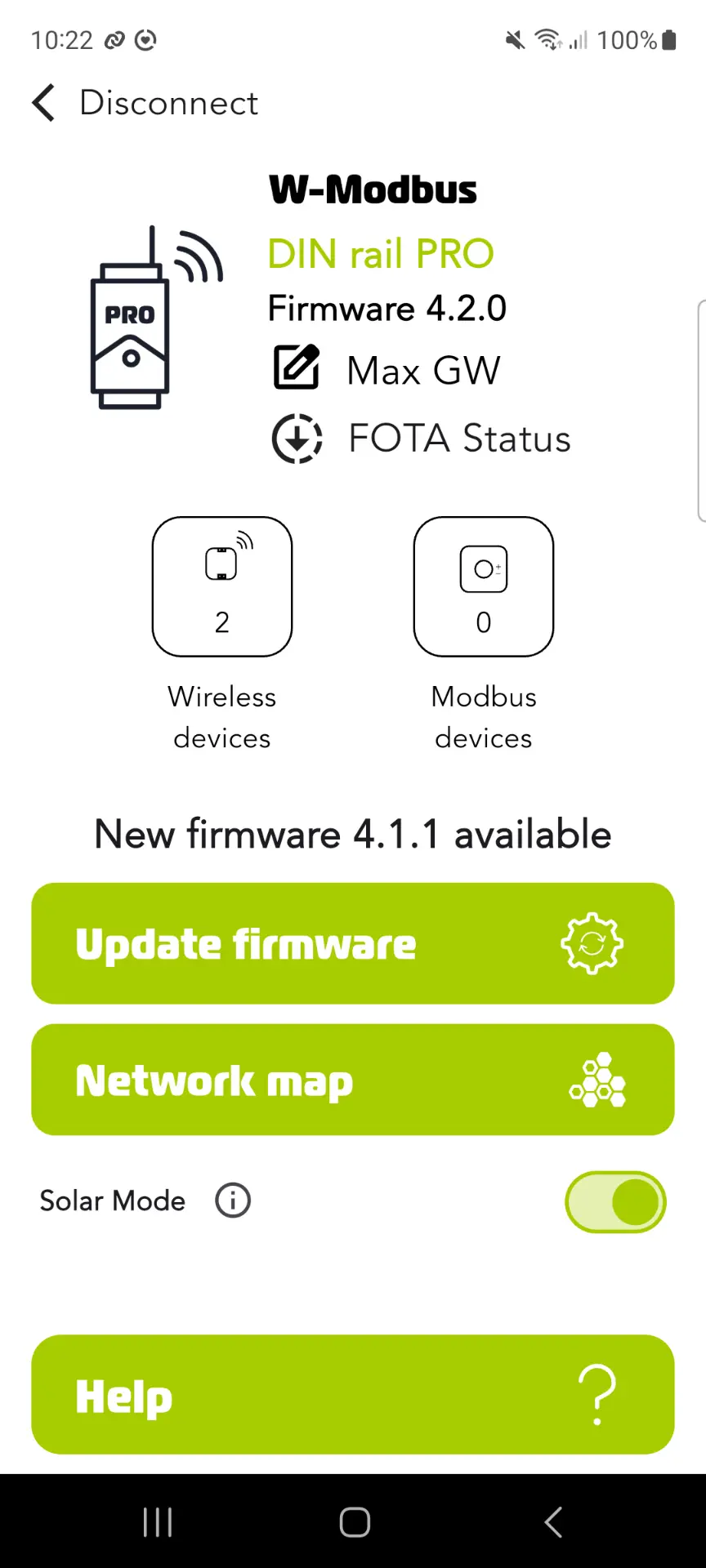
FW major version |
| 33 |
INT |
R |
|
|
FW minor version |
| 34 |
INT |
R |
|
|
FW patch version |
| 35 |
INT |
R |
|
|
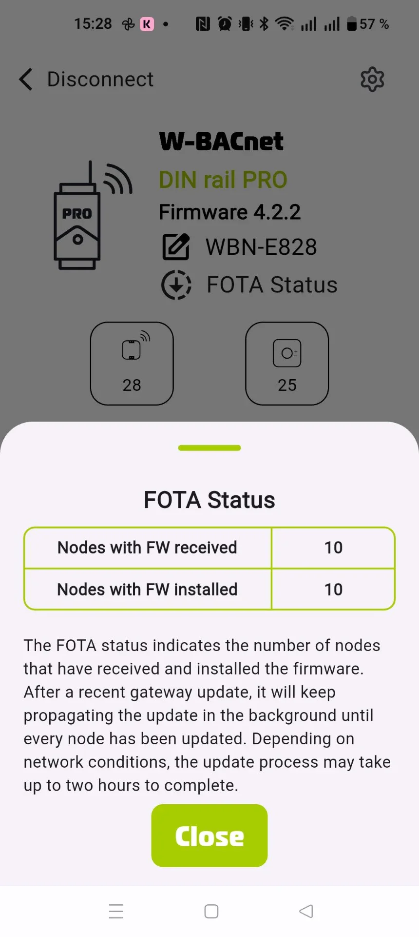
Number of nodes that received the latest firmware |
| 36 |
INT |
R |
|
|
Number of nodes that installed the latest firmware |
| 37 |
INT |
R |
(0, 1) |
|
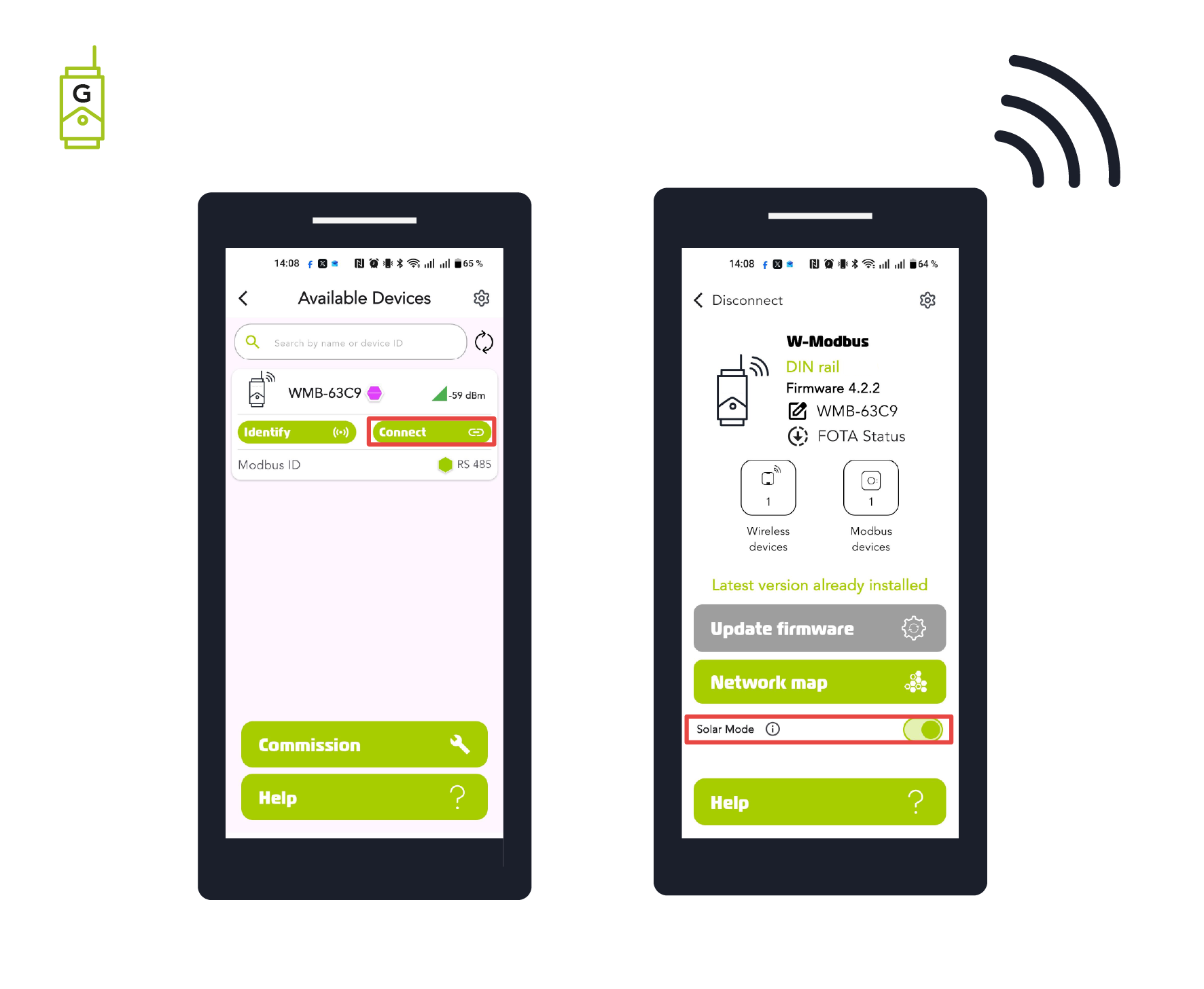
Solar application mode enabled |
| 38 |
INT |
R |
|
|
Git commit hash, characters 1-2 (2 ASCII chars, big-endian) |
| 39 |
INT |
R |
|
|
Git commit hash, characters 3-4 (2 ASCII chars, big-endian) |
| 40 |
INT |
R |
|
|
Git commit hash, characters 5-6 (2 ASCII chars, big-endian) |
| 41 |
INT |
R |
|
|
Git commit hash, characters 7-8 (2 ASCII chars, big-endian) |
| 50 |
INT |
R |
|
|
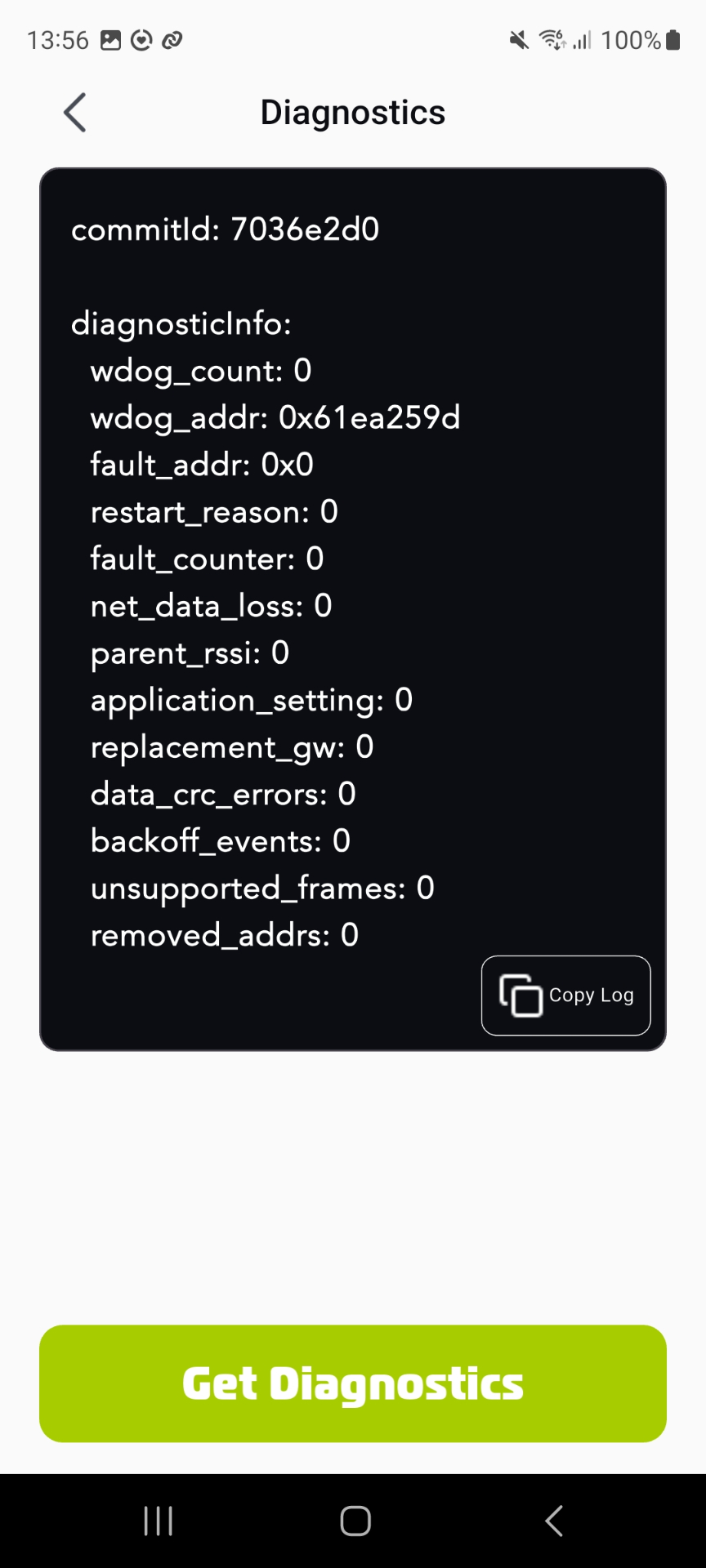
Watchdog reset counter |
| 51 |
INT |
R |
|
|
Fault handler PC, low 16 bits |
| 53 |
INT |
R |
|
|
Fault handler PC, high 16 bits |
| 55 |
INT |
R |
|
|
Last restart reason |
| 56 |
INT |
R |
|
|
Fault handler reset counter |
| 57 |
INT |
R |
|
|
RSSI to parent node |
| 58 |
INT |
R |
(0, 1) |
|
1 if the gateway is a replacement, 0 otherwise |
| 59 |
INT |
R |
|
|
Uptime in hours, high 16 bits |
| 60 |
INT |
R |
|
|
Uptime in hours, low 16 bits |
| 61 |
INT |
R |
|
|
Gateway recovery code, word 1 of 16 (2 bytes, big-endian) |
| 62 |
INT |
R |
|
|
Gateway recovery code, word 2 of 16 (2 bytes, big-endian) |
| 63 |
INT |
R |
|
|
Gateway recovery code, word 3 of 16 (2 bytes, big-endian) |
| 64 |
INT |
R |
|
|
Gateway recovery code, word 4 of 16 (2 bytes, big-endian) |
| 65 |
INT |
R |
|
|
Gateway recovery code, word 5 of 16 (2 bytes, big-endian) |
| 66 |
INT |
R |
|
|
Gateway recovery code, word 6 of 16 (2 bytes, big-endian) |
| 67 |
INT |
R |
|
|
Gateway recovery code, word 7 of 16 (2 bytes, big-endian) |
| 68 |
INT |
R |
|
|
Gateway recovery code, word 8 of 16 (2 bytes, big-endian) |
| 69 |
INT |
R |
|
|
Gateway recovery code, word 9 of 16 (2 bytes, big-endian) |
| 70 |
INT |
R |
|
|
Gateway recovery code, word 10 of 16 (2 bytes, big-endian) |
| 71 |
INT |
R |
|
|
Gateway recovery code, word 11 of 16 (2 bytes, big-endian) |
| 72 |
INT |
R |
|
|
Gateway recovery code, word 12 of 16 (2 bytes, big-endian) |
| 73 |
INT |
R |
|
|
Gateway recovery code, word 13 of 16 (2 bytes, big-endian) |
| 74 |
INT |
R |
|
|
Gateway recovery code, word 14 of 16 (2 bytes, big-endian) |
| 75 |
INT |
R |
|
|
Gateway recovery code, word 15 of 16 (2 bytes, big-endian) |
| 76 |
INT |
R |
|
|
Gateway recovery code, word 16 of 16 (2 bytes, big-endian) |
| 101 |
INT |
R |
(0, 100) |
0 |
Packet delivery ratio to root for node index 0 (255 = no valid link) |
| 102 |
INT |
R |
(0, 100) |
0 |
Packet delivery ratio to root for node index 1 (255 = no valid link) |
| 103 |
INT |
R |
(0, 100) |
0 |
Packet delivery ratio to root for node index 2 (255 = no valid link) |
| 104 |
INT |
R |
(0, 100) |
0 |
Packet delivery ratio to root for node index 3 (255 = no valid link) |
| 105 |
INT |
R |
(0, 100) |
0 |
Packet delivery ratio to root for node index 4 (255 = no valid link) |
| 106 |
INT |
R |
(0, 100) |
0 |
Packet delivery ratio to root for node index 5 (255 = no valid link) |
| 107 |
INT |
R |
(0, 100) |
0 |
Packet delivery ratio to root for node index 6 (255 = no valid link) |
| 108 |
INT |
R |
(0, 100) |
0 |
Packet delivery ratio to root for node index 7 (255 = no valid link) |
| 109 |
INT |
R |
(0, 100) |
0 |
Packet delivery ratio to root for node index 8 (255 = no valid link) |
| 110 |
INT |
R |
(0, 100) |
0 |
Packet delivery ratio to root for node index 9 (255 = no valid link) |
| 111 |
INT |
R |
(0, 100) |
0 |
Packet delivery ratio to root for node index 10 (255 = no valid link) |
| 112 |
INT |
R |
(0, 100) |
0 |
Packet delivery ratio to root for node index 11 (255 = no valid link) |
| 113 |
INT |
R |
(0, 100) |
0 |
Packet delivery ratio to root for node index 12 (255 = no valid link) |
| 114 |
INT |
R |
(0, 100) |
0 |
Packet delivery ratio to root for node index 13 (255 = no valid link) |
| 115 |
INT |
R |
(0, 100) |
0 |
Packet delivery ratio to root for node index 14 (255 = no valid link) |
| 116 |
INT |
R |
(0, 100) |
0 |
Packet delivery ratio to root for node index 15 (255 = no valid link) |
| 117 |
INT |
R |
(0, 100) |
0 |
Packet delivery ratio to root for node index 16 (255 = no valid link) |
| 118 |
INT |
R |
(0, 100) |
0 |
Packet delivery ratio to root for node index 17 (255 = no valid link) |
| 119 |
INT |
R |
(0, 100) |
0 |
Packet delivery ratio to root for node index 18 (255 = no valid link) |
| 120 |
INT |
R |
(0, 100) |
0 |
Packet delivery ratio to root for node index 19 (255 = no valid link) |
| 121 |
INT |
R |
(0, 100) |
0 |
Packet delivery ratio to root for node index 20 (255 = no valid link) |
| 122 |
INT |
R |
(0, 100) |
0 |
Packet delivery ratio to root for node index 21 (255 = no valid link) |
| 123 |
INT |
R |
(0, 100) |
0 |
Packet delivery ratio to root for node index 22 (255 = no valid link) |
| 124 |
INT |
R |
(0, 100) |
0 |
Packet delivery ratio to root for node index 23 (255 = no valid link) |
| 125 |
INT |
R |
(0, 100) |
0 |
Packet delivery ratio to root for node index 24 (255 = no valid link) |
| 126 |
INT |
R |
(0, 100) |
0 |
Packet delivery ratio to root for node index 25 (255 = no valid link) |
| 127 |
INT |
R |
(0, 100) |
0 |
Packet delivery ratio to root for node index 26 (255 = no valid link) |
| 128 |
INT |
R |
(0, 100) |
0 |
Packet delivery ratio to root for node index 27 (255 = no valid link) |
| 129 |
INT |
R |
(0, 100) |
0 |
Packet delivery ratio to root for node index 28 (255 = no valid link) |
| 130 |
INT |
R |
(0, 100) |
0 |
Packet delivery ratio to root for node index 29 (255 = no valid link) |
| 131 |
INT |
R |
(0, 100) |
0 |
Packet delivery ratio to root for node index 30 (255 = no valid link) |
| 132 |
INT |
R |
(0, 100) |
0 |
Packet delivery ratio to root for node index 31 (255 = no valid link) |
| 133 |
INT |
R |
(0, 100) |
0 |
Packet delivery ratio to root for node index 32 (255 = no valid link) |
| 134 |
INT |
R |
(0, 100) |
0 |
Packet delivery ratio to root for node index 33 (255 = no valid link) |
| 135 |
INT |
R |
(0, 100) |
0 |
Packet delivery ratio to root for node index 34 (255 = no valid link) |
| 136 |
INT |
R |
(0, 100) |
0 |
Packet delivery ratio to root for node index 35 (255 = no valid link) |
| 137 |
INT |
R |
(0, 100) |
0 |
Packet delivery ratio to root for node index 36 (255 = no valid link) |
| 138 |
INT |
R |
(0, 100) |
0 |
Packet delivery ratio to root for node index 37 (255 = no valid link) |
| 139 |
INT |
R |
(0, 100) |
0 |
Packet delivery ratio to root for node index 38 (255 = no valid link) |
| 140 |
INT |
R |
(0, 100) |
0 |
Packet delivery ratio to root for node index 39 (255 = no valid link) |
| 141 |
INT |
R |
(0, 100) |
0 |
Packet delivery ratio to root for node index 40 (255 = no valid link) |
| 142 |
INT |
R |
(0, 100) |
0 |
Packet delivery ratio to root for node index 41 (255 = no valid link) |
| 143 |
INT |
R |
(0, 100) |
0 |
Packet delivery ratio to root for node index 42 (255 = no valid link) |
| 144 |
INT |
R |
(0, 100) |
0 |
Packet delivery ratio to root for node index 43 (255 = no valid link) |
| 145 |
INT |
R |
(0, 100) |
0 |
Packet delivery ratio to root for node index 44 (255 = no valid link) |
| 146 |
INT |
R |
(0, 100) |
0 |
Packet delivery ratio to root for node index 45 (255 = no valid link) |
| 147 |
INT |
R |
(0, 100) |
0 |
Packet delivery ratio to root for node index 46 (255 = no valid link) |
| 148 |
INT |
R |
(0, 100) |
0 |
Packet delivery ratio to root for node index 47 (255 = no valid link) |
| 149 |
INT |
R |
(0, 100) |
0 |
Packet delivery ratio to root for node index 48 (255 = no valid link) |
| 150 |
INT |
R |
(0, 100) |
0 |
Packet delivery ratio to root for node index 49 (255 = no valid link) |
| 151 |
INT |
R |
(0, 100) |
0 |
Packet delivery ratio to root for node index 50 (255 = no valid link) |
| 152 |
INT |
R |
(0, 100) |
0 |
Packet delivery ratio to root for node index 51 (255 = no valid link) |
| 153 |
INT |
R |
(0, 100) |
0 |
Packet delivery ratio to root for node index 52 (255 = no valid link) |
| 154 |
INT |
R |
(0, 100) |
0 |
Packet delivery ratio to root for node index 53 (255 = no valid link) |
| 155 |
INT |
R |
(0, 100) |
0 |
Packet delivery ratio to root for node index 54 (255 = no valid link) |
| 156 |
INT |
R |
(0, 100) |
0 |
Packet delivery ratio to root for node index 55 (255 = no valid link) |
| 157 |
INT |
R |
(0, 100) |
0 |
Packet delivery ratio to root for node index 56 (255 = no valid link) |
| 158 |
INT |
R |
(0, 100) |
0 |
Packet delivery ratio to root for node index 57 (255 = no valid link) |
| 159 |
INT |
R |
(0, 100) |
0 |
Packet delivery ratio to root for node index 58 (255 = no valid link) |
| 160 |
INT |
R |
(0, 100) |
0 |
Packet delivery ratio to root for node index 59 (255 = no valid link) |
| 161 |
INT |
R |
(0, 100) |
0 |
Packet delivery ratio to root for node index 60 (255 = no valid link) |
| 162 |
INT |
R |
(0, 100) |
0 |
Packet delivery ratio to root for node index 61 (255 = no valid link) |
| 163 |
INT |
R |
(0, 100) |
0 |
Packet delivery ratio to root for node index 62 (255 = no valid link) |
| 164 |
INT |
R |
(0, 100) |
0 |
Packet delivery ratio to root for node index 63 (255 = no valid link) |
| 165 |
INT |
R |
(0, 100) |
0 |
Packet delivery ratio to root for node index 64 (255 = no valid link) |
| 166 |
INT |
R |
(0, 100) |
0 |
Packet delivery ratio to root for node index 65 (255 = no valid link) |
| 167 |
INT |
R |
(0, 100) |
0 |
Packet delivery ratio to root for node index 66 (255 = no valid link) |
| 168 |
INT |
R |
(0, 100) |
0 |
Packet delivery ratio to root for node index 67 (255 = no valid link) |
| 169 |
INT |
R |
(0, 100) |
0 |
Packet delivery ratio to root for node index 68 (255 = no valid link) |
| 170 |
INT |
R |
(0, 100) |
0 |
Packet delivery ratio to root for node index 69 (255 = no valid link) |
| 171 |
INT |
R |
(0, 100) |
0 |
Packet delivery ratio to root for node index 70 (255 = no valid link) |
| 172 |
INT |
R |
(0, 100) |
0 |
Packet delivery ratio to root for node index 71 (255 = no valid link) |
| 173 |
INT |
R |
(0, 100) |
0 |
Packet delivery ratio to root for node index 72 (255 = no valid link) |
| 174 |
INT |
R |
(0, 100) |
0 |
Packet delivery ratio to root for node index 73 (255 = no valid link) |
| 175 |
INT |
R |
(0, 100) |
0 |
Packet delivery ratio to root for node index 74 (255 = no valid link) |
| 176 |
INT |
R |
(0, 100) |
0 |
Packet delivery ratio to root for node index 75 (255 = no valid link) |
| 177 |
INT |
R |
(0, 100) |
0 |
Packet delivery ratio to root for node index 76 (255 = no valid link) |
| 178 |
INT |
R |
(0, 100) |
0 |
Packet delivery ratio to root for node index 77 (255 = no valid link) |
| 179 |
INT |
R |
(0, 100) |
0 |
Packet delivery ratio to root for node index 78 (255 = no valid link) |
| 180 |
INT |
R |
(0, 100) |
0 |
Packet delivery ratio to root for node index 79 (255 = no valid link) |
| 181 |
INT |
R |
(0, 100) |
0 |
Packet delivery ratio to root for node index 80 (255 = no valid link) |
| 182 |
INT |
R |
(0, 100) |
0 |
Packet delivery ratio to root for node index 81 (255 = no valid link) |
| 183 |
INT |
R |
(0, 100) |
0 |
Packet delivery ratio to root for node index 82 (255 = no valid link) |
| 184 |
INT |
R |
(0, 100) |
0 |
Packet delivery ratio to root for node index 83 (255 = no valid link) |
| 185 |
INT |
R |
(0, 100) |
0 |
Packet delivery ratio to root for node index 84 (255 = no valid link) |
| 186 |
INT |
R |
(0, 100) |
0 |
Packet delivery ratio to root for node index 85 (255 = no valid link) |
| 187 |
INT |
R |
(0, 100) |
0 |
Packet delivery ratio to root for node index 86 (255 = no valid link) |
| 188 |
INT |
R |
(0, 100) |
0 |
Packet delivery ratio to root for node index 87 (255 = no valid link) |
| 189 |
INT |
R |
(0, 100) |
0 |
Packet delivery ratio to root for node index 88 (255 = no valid link) |
| 190 |
INT |
R |
(0, 100) |
0 |
Packet delivery ratio to root for node index 89 (255 = no valid link) |
| 191 |
INT |
R |
(0, 100) |
0 |
Packet delivery ratio to root for node index 90 (255 = no valid link) |
| 192 |
INT |
R |
(0, 100) |
0 |
Packet delivery ratio to root for node index 91 (255 = no valid link) |
| 193 |
INT |
R |
(0, 100) |
0 |
Packet delivery ratio to root for node index 92 (255 = no valid link) |
| 194 |
INT |
R |
(0, 100) |
0 |
Packet delivery ratio to root for node index 93 (255 = no valid link) |
| 195 |
INT |
R |
(0, 100) |
0 |
Packet delivery ratio to root for node index 94 (255 = no valid link) |
| 196 |
INT |
R |
(0, 100) |
0 |
Packet delivery ratio to root for node index 95 (255 = no valid link) |
| 197 |
INT |
R |
(0, 100) |
0 |
Packet delivery ratio to root for node index 96 (255 = no valid link) |
| 198 |
INT |
R |
(0, 100) |
0 |
Packet delivery ratio to root for node index 97 (255 = no valid link) |
| 199 |
INT |
R |
(0, 100) |
0 |
Packet delivery ratio to root for node index 98 (255 = no valid link) |
| 200 |
INT |
R |
(0, 100) |
0 |
Packet delivery ratio to root for node index 99 (255 = no valid link) |
| 301 |
INT |
R |
|
0 |
Parent node ID for node index 0 (255 = direct link to root) |
| 302 |
INT |
R |
|
0 |
Parent node ID for node index 1 (255 = direct link to root) |
| 303 |
INT |
R |
|
0 |
Parent node ID for node index 2 (255 = direct link to root) |
| 304 |
INT |
R |
|
0 |
Parent node ID for node index 3 (255 = direct link to root) |
| 305 |
INT |
R |
|
0 |
Parent node ID for node index 4 (255 = direct link to root) |
| 306 |
INT |
R |
|
0 |
Parent node ID for node index 5 (255 = direct link to root) |
| 307 |
INT |
R |
|
0 |
Parent node ID for node index 6 (255 = direct link to root) |
| 308 |
INT |
R |
|
0 |
Parent node ID for node index 7 (255 = direct link to root) |
| 309 |
INT |
R |
|
0 |
Parent node ID for node index 8 (255 = direct link to root) |
| 310 |
INT |
R |
|
0 |
Parent node ID for node index 9 (255 = direct link to root) |
| 311 |
INT |
R |
|
0 |
Parent node ID for node index 10 (255 = direct link to root) |
| 312 |
INT |
R |
|
0 |
Parent node ID for node index 11 (255 = direct link to root) |
| 313 |
INT |
R |
|
0 |
Parent node ID for node index 12 (255 = direct link to root) |
| 314 |
INT |
R |
|
0 |
Parent node ID for node index 13 (255 = direct link to root) |
| 315 |
INT |
R |
|
0 |
Parent node ID for node index 14 (255 = direct link to root) |
| 316 |
INT |
R |
|
0 |
Parent node ID for node index 15 (255 = direct link to root) |
| 317 |
INT |
R |
|
0 |
Parent node ID for node index 16 (255 = direct link to root) |
| 318 |
INT |
R |
|
0 |
Parent node ID for node index 17 (255 = direct link to root) |
| 319 |
INT |
R |
|
0 |
Parent node ID for node index 18 (255 = direct link to root) |
| 320 |
INT |
R |
|
0 |
Parent node ID for node index 19 (255 = direct link to root) |
| 321 |
INT |
R |
|
0 |
Parent node ID for node index 20 (255 = direct link to root) |
| 322 |
INT |
R |
|
0 |
Parent node ID for node index 21 (255 = direct link to root) |
| 323 |
INT |
R |
|
0 |
Parent node ID for node index 22 (255 = direct link to root) |
| 324 |
INT |
R |
|
0 |
Parent node ID for node index 23 (255 = direct link to root) |
| 325 |
INT |
R |
|
0 |
Parent node ID for node index 24 (255 = direct link to root) |
| 326 |
INT |
R |
|
0 |
Parent node ID for node index 25 (255 = direct link to root) |
| 327 |
INT |
R |
|
0 |
Parent node ID for node index 26 (255 = direct link to root) |
| 328 |
INT |
R |
|
0 |
Parent node ID for node index 27 (255 = direct link to root) |
| 329 |
INT |
R |
|
0 |
Parent node ID for node index 28 (255 = direct link to root) |
| 330 |
INT |
R |
|
0 |
Parent node ID for node index 29 (255 = direct link to root) |
| 331 |
INT |
R |
|
0 |
Parent node ID for node index 30 (255 = direct link to root) |
| 332 |
INT |
R |
|
0 |
Parent node ID for node index 31 (255 = direct link to root) |
| 333 |
INT |
R |
|
0 |
Parent node ID for node index 32 (255 = direct link to root) |
| 334 |
INT |
R |
|
0 |
Parent node ID for node index 33 (255 = direct link to root) |
| 335 |
INT |
R |
|
0 |
Parent node ID for node index 34 (255 = direct link to root) |
| 336 |
INT |
R |
|
0 |
Parent node ID for node index 35 (255 = direct link to root) |
| 337 |
INT |
R |
|
0 |
Parent node ID for node index 36 (255 = direct link to root) |
| 338 |
INT |
R |
|
0 |
Parent node ID for node index 37 (255 = direct link to root) |
| 339 |
INT |
R |
|
0 |
Parent node ID for node index 38 (255 = direct link to root) |
| 340 |
INT |
R |
|
0 |
Parent node ID for node index 39 (255 = direct link to root) |
| 341 |
INT |
R |
|
0 |
Parent node ID for node index 40 (255 = direct link to root) |
| 342 |
INT |
R |
|
0 |
Parent node ID for node index 41 (255 = direct link to root) |
| 343 |
INT |
R |
|
0 |
Parent node ID for node index 42 (255 = direct link to root) |
| 344 |
INT |
R |
|
0 |
Parent node ID for node index 43 (255 = direct link to root) |
| 345 |
INT |
R |
|
0 |
Parent node ID for node index 44 (255 = direct link to root) |
| 346 |
INT |
R |
|
0 |
Parent node ID for node index 45 (255 = direct link to root) |
| 347 |
INT |
R |
|
0 |
Parent node ID for node index 46 (255 = direct link to root) |
| 348 |
INT |
R |
|
0 |
Parent node ID for node index 47 (255 = direct link to root) |
| 349 |
INT |
R |
|
0 |
Parent node ID for node index 48 (255 = direct link to root) |
| 350 |
INT |
R |
|
0 |
Parent node ID for node index 49 (255 = direct link to root) |
| 351 |
INT |
R |
|
0 |
Parent node ID for node index 50 (255 = direct link to root) |
| 352 |
INT |
R |
|
0 |
Parent node ID for node index 51 (255 = direct link to root) |
| 353 |
INT |
R |
|
0 |
Parent node ID for node index 52 (255 = direct link to root) |
| 354 |
INT |
R |
|
0 |
Parent node ID for node index 53 (255 = direct link to root) |
| 355 |
INT |
R |
|
0 |
Parent node ID for node index 54 (255 = direct link to root) |
| 356 |
INT |
R |
|
0 |
Parent node ID for node index 55 (255 = direct link to root) |
| 357 |
INT |
R |
|
0 |
Parent node ID for node index 56 (255 = direct link to root) |
| 358 |
INT |
R |
|
0 |
Parent node ID for node index 57 (255 = direct link to root) |
| 359 |
INT |
R |
|
0 |
Parent node ID for node index 58 (255 = direct link to root) |
| 360 |
INT |
R |
|
0 |
Parent node ID for node index 59 (255 = direct link to root) |
| 361 |
INT |
R |
|
0 |
Parent node ID for node index 60 (255 = direct link to root) |
| 362 |
INT |
R |
|
0 |
Parent node ID for node index 61 (255 = direct link to root) |
| 363 |
INT |
R |
|
0 |
Parent node ID for node index 62 (255 = direct link to root) |
| 364 |
INT |
R |
|
0 |
Parent node ID for node index 63 (255 = direct link to root) |
| 365 |
INT |
R |
|
0 |
Parent node ID for node index 64 (255 = direct link to root) |
| 366 |
INT |
R |
|
0 |
Parent node ID for node index 65 (255 = direct link to root) |
| 367 |
INT |
R |
|
0 |
Parent node ID for node index 66 (255 = direct link to root) |
| 368 |
INT |
R |
|
0 |
Parent node ID for node index 67 (255 = direct link to root) |
| 369 |
INT |
R |
|
0 |
Parent node ID for node index 68 (255 = direct link to root) |
| 370 |
INT |
R |
|
0 |
Parent node ID for node index 69 (255 = direct link to root) |
| 371 |
INT |
R |
|
0 |
Parent node ID for node index 70 (255 = direct link to root) |
| 372 |
INT |
R |
|
0 |
Parent node ID for node index 71 (255 = direct link to root) |
| 373 |
INT |
R |
|
0 |
Parent node ID for node index 72 (255 = direct link to root) |
| 374 |
INT |
R |
|
0 |
Parent node ID for node index 73 (255 = direct link to root) |
| 375 |
INT |
R |
|
0 |
Parent node ID for node index 74 (255 = direct link to root) |
| 376 |
INT |
R |
|
0 |
Parent node ID for node index 75 (255 = direct link to root) |
| 377 |
INT |
R |
|
0 |
Parent node ID for node index 76 (255 = direct link to root) |
| 378 |
INT |
R |
|
0 |
Parent node ID for node index 77 (255 = direct link to root) |
| 379 |
INT |
R |
|
0 |
Parent node ID for node index 78 (255 = direct link to root) |
| 380 |
INT |
R |
|
0 |
Parent node ID for node index 79 (255 = direct link to root) |
| 381 |
INT |
R |
|
0 |
Parent node ID for node index 80 (255 = direct link to root) |
| 382 |
INT |
R |
|
0 |
Parent node ID for node index 81 (255 = direct link to root) |
| 383 |
INT |
R |
|
0 |
Parent node ID for node index 82 (255 = direct link to root) |
| 384 |
INT |
R |
|
0 |
Parent node ID for node index 83 (255 = direct link to root) |
| 385 |
INT |
R |
|
0 |
Parent node ID for node index 84 (255 = direct link to root) |
| 386 |
INT |
R |
|
0 |
Parent node ID for node index 85 (255 = direct link to root) |
| 387 |
INT |
R |
|
0 |
Parent node ID for node index 86 (255 = direct link to root) |
| 388 |
INT |
R |
|
0 |
Parent node ID for node index 87 (255 = direct link to root) |
| 389 |
INT |
R |
|
0 |
Parent node ID for node index 88 (255 = direct link to root) |
| 390 |
INT |
R |
|
0 |
Parent node ID for node index 89 (255 = direct link to root) |
| 391 |
INT |
R |
|
0 |
Parent node ID for node index 90 (255 = direct link to root) |
| 392 |
INT |
R |
|
0 |
Parent node ID for node index 91 (255 = direct link to root) |
| 393 |
INT |
R |
|
0 |
Parent node ID for node index 92 (255 = direct link to root) |
| 394 |
INT |
R |
|
0 |
Parent node ID for node index 93 (255 = direct link to root) |
| 395 |
INT |
R |
|
0 |
Parent node ID for node index 94 (255 = direct link to root) |
| 396 |
INT |
R |
|
0 |
Parent node ID for node index 95 (255 = direct link to root) |
| 397 |
INT |
R |
|
0 |
Parent node ID for node index 96 (255 = direct link to root) |
| 398 |
INT |
R |
|
0 |
Parent node ID for node index 97 (255 = direct link to root) |
| 399 |
INT |
R |
|
0 |
Parent node ID for node index 98 (255 = direct link to root) |
| 400 |
INT |
R |
|
0 |
Parent node ID for node index 99 (255 = direct link to root) |
| 501 |
INT |
R |
(0, 24) |
0 |
RS485 bus configuration for node index 0 |
| 502 |
INT |
R |
(0, 24) |
0 |
RS485 bus configuration for node index 1 |
| 503 |
INT |
R |
(0, 24) |
0 |
RS485 bus configuration for node index 2 |
| 504 |
INT |
R |
(0, 24) |
0 |
RS485 bus configuration for node index 3 |
| 505 |
INT |
R |
(0, 24) |
0 |
RS485 bus configuration for node index 4 |
| 506 |
INT |
R |
(0, 24) |
0 |
RS485 bus configuration for node index 5 |
| 507 |
INT |
R |
(0, 24) |
0 |
RS485 bus configuration for node index 6 |
| 508 |
INT |
R |
(0, 24) |
0 |
RS485 bus configuration for node index 7 |
| 509 |
INT |
R |
(0, 24) |
0 |
RS485 bus configuration for node index 8 |
| 510 |
INT |
R |
(0, 24) |
0 |
RS485 bus configuration for node index 9 |
| 511 |
INT |
R |
(0, 24) |
0 |
RS485 bus configuration for node index 10 |
| 512 |
INT |
R |
(0, 24) |
0 |
RS485 bus configuration for node index 11 |
| 513 |
INT |
R |
(0, 24) |
0 |
RS485 bus configuration for node index 12 |
| 514 |
INT |
R |
(0, 24) |
0 |
RS485 bus configuration for node index 13 |
| 515 |
INT |
R |
(0, 24) |
0 |
RS485 bus configuration for node index 14 |
| 516 |
INT |
R |
(0, 24) |
0 |
RS485 bus configuration for node index 15 |
| 517 |
INT |
R |
(0, 24) |
0 |
RS485 bus configuration for node index 16 |
| 518 |
INT |
R |
(0, 24) |
0 |
RS485 bus configuration for node index 17 |
| 519 |
INT |
R |
(0, 24) |
0 |
RS485 bus configuration for node index 18 |
| 520 |
INT |
R |
(0, 24) |
0 |
RS485 bus configuration for node index 19 |
| 521 |
INT |
R |
(0, 24) |
0 |
RS485 bus configuration for node index 20 |
| 522 |
INT |
R |
(0, 24) |
0 |
RS485 bus configuration for node index 21 |
| 523 |
INT |
R |
(0, 24) |
0 |
RS485 bus configuration for node index 22 |
| 524 |
INT |
R |
(0, 24) |
0 |
RS485 bus configuration for node index 23 |
| 525 |
INT |
R |
(0, 24) |
0 |
RS485 bus configuration for node index 24 |
| 526 |
INT |
R |
(0, 24) |
0 |
RS485 bus configuration for node index 25 |
| 527 |
INT |
R |
(0, 24) |
0 |
RS485 bus configuration for node index 26 |
| 528 |
INT |
R |
(0, 24) |
0 |
RS485 bus configuration for node index 27 |
| 529 |
INT |
R |
(0, 24) |
0 |
RS485 bus configuration for node index 28 |
| 530 |
INT |
R |
(0, 24) |
0 |
RS485 bus configuration for node index 29 |
| 531 |
INT |
R |
(0, 24) |
0 |
RS485 bus configuration for node index 30 |
| 532 |
INT |
R |
(0, 24) |
0 |
RS485 bus configuration for node index 31 |
| 533 |
INT |
R |
(0, 24) |
0 |
RS485 bus configuration for node index 32 |
| 534 |
INT |
R |
(0, 24) |
0 |
RS485 bus configuration for node index 33 |
| 535 |
INT |
R |
(0, 24) |
0 |
RS485 bus configuration for node index 34 |
| 536 |
INT |
R |
(0, 24) |
0 |
RS485 bus configuration for node index 35 |
| 537 |
INT |
R |
(0, 24) |
0 |
RS485 bus configuration for node index 36 |
| 538 |
INT |
R |
(0, 24) |
0 |
RS485 bus configuration for node index 37 |
| 539 |
INT |
R |
(0, 24) |
0 |
RS485 bus configuration for node index 38 |
| 540 |
INT |
R |
(0, 24) |
0 |
RS485 bus configuration for node index 39 |
| 541 |
INT |
R |
(0, 24) |
0 |
RS485 bus configuration for node index 40 |
| 542 |
INT |
R |
(0, 24) |
0 |
RS485 bus configuration for node index 41 |
| 543 |
INT |
R |
(0, 24) |
0 |
RS485 bus configuration for node index 42 |
| 544 |
INT |
R |
(0, 24) |
0 |
RS485 bus configuration for node index 43 |
| 545 |
INT |
R |
(0, 24) |
0 |
RS485 bus configuration for node index 44 |
| 546 |
INT |
R |
(0, 24) |
0 |
RS485 bus configuration for node index 45 |
| 547 |
INT |
R |
(0, 24) |
0 |
RS485 bus configuration for node index 46 |
| 548 |
INT |
R |
(0, 24) |
0 |
RS485 bus configuration for node index 47 |
| 549 |
INT |
R |
(0, 24) |
0 |
RS485 bus configuration for node index 48 |
| 550 |
INT |
R |
(0, 24) |
0 |
RS485 bus configuration for node index 49 |
| 551 |
INT |
R |
(0, 24) |
0 |
RS485 bus configuration for node index 50 |
| 552 |
INT |
R |
(0, 24) |
0 |
RS485 bus configuration for node index 51 |
| 553 |
INT |
R |
(0, 24) |
0 |
RS485 bus configuration for node index 52 |
| 554 |
INT |
R |
(0, 24) |
0 |
RS485 bus configuration for node index 53 |
| 555 |
INT |
R |
(0, 24) |
0 |
RS485 bus configuration for node index 54 |
| 556 |
INT |
R |
(0, 24) |
0 |
RS485 bus configuration for node index 55 |
| 557 |
INT |
R |
(0, 24) |
0 |
RS485 bus configuration for node index 56 |
| 558 |
INT |
R |
(0, 24) |
0 |
RS485 bus configuration for node index 57 |
| 559 |
INT |
R |
(0, 24) |
0 |
RS485 bus configuration for node index 58 |
| 560 |
INT |
R |
(0, 24) |
0 |
RS485 bus configuration for node index 59 |
| 561 |
INT |
R |
(0, 24) |
0 |
RS485 bus configuration for node index 60 |
| 562 |
INT |
R |
(0, 24) |
0 |
RS485 bus configuration for node index 61 |
| 563 |
INT |
R |
(0, 24) |
0 |
RS485 bus configuration for node index 62 |
| 564 |
INT |
R |
(0, 24) |
0 |
RS485 bus configuration for node index 63 |
| 565 |
INT |
R |
(0, 24) |
0 |
RS485 bus configuration for node index 64 |
| 566 |
INT |
R |
(0, 24) |
0 |
RS485 bus configuration for node index 65 |
| 567 |
INT |
R |
(0, 24) |
0 |
RS485 bus configuration for node index 66 |
| 568 |
INT |
R |
(0, 24) |
0 |
RS485 bus configuration for node index 67 |
| 569 |
INT |
R |
(0, 24) |
0 |
RS485 bus configuration for node index 68 |
| 570 |
INT |
R |
(0, 24) |
0 |
RS485 bus configuration for node index 69 |
| 571 |
INT |
R |
(0, 24) |
0 |
RS485 bus configuration for node index 70 |
| 572 |
INT |
R |
(0, 24) |
0 |
RS485 bus configuration for node index 71 |
| 573 |
INT |
R |
(0, 24) |
0 |
RS485 bus configuration for node index 72 |
| 574 |
INT |
R |
(0, 24) |
0 |
RS485 bus configuration for node index 73 |
| 575 |
INT |
R |
(0, 24) |
0 |
RS485 bus configuration for node index 74 |
| 576 |
INT |
R |
(0, 24) |
0 |
RS485 bus configuration for node index 75 |
| 577 |
INT |
R |
(0, 24) |
0 |
RS485 bus configuration for node index 76 |
| 578 |
INT |
R |
(0, 24) |
0 |
RS485 bus configuration for node index 77 |
| 579 |
INT |
R |
(0, 24) |
0 |
RS485 bus configuration for node index 78 |
| 580 |
INT |
R |
(0, 24) |
0 |
RS485 bus configuration for node index 79 |
| 581 |
INT |
R |
(0, 24) |
0 |
RS485 bus configuration for node index 80 |
| 582 |
INT |
R |
(0, 24) |
0 |
RS485 bus configuration for node index 81 |
| 583 |
INT |
R |
(0, 24) |
0 |
RS485 bus configuration for node index 82 |
| 584 |
INT |
R |
(0, 24) |
0 |
RS485 bus configuration for node index 83 |
| 585 |
INT |
R |
(0, 24) |
0 |
RS485 bus configuration for node index 84 |
| 586 |
INT |
R |
(0, 24) |
0 |
RS485 bus configuration for node index 85 |
| 587 |
INT |
R |
(0, 24) |
0 |
RS485 bus configuration for node index 86 |
| 588 |
INT |
R |
(0, 24) |
0 |
RS485 bus configuration for node index 87 |
| 589 |
INT |
R |
(0, 24) |
0 |
RS485 bus configuration for node index 88 |
| 590 |
INT |
R |
(0, 24) |
0 |
RS485 bus configuration for node index 89 |
| 591 |
INT |
R |
(0, 24) |
0 |
RS485 bus configuration for node index 90 |
| 592 |
INT |
R |
(0, 24) |
0 |
RS485 bus configuration for node index 91 |
| 593 |
INT |
R |
(0, 24) |
0 |
RS485 bus configuration for node index 92 |
| 594 |
INT |
R |
(0, 24) |
0 |
RS485 bus configuration for node index 93 |
| 595 |
INT |
R |
(0, 24) |
0 |
RS485 bus configuration for node index 94 |
| 596 |
INT |
R |
(0, 24) |
0 |
RS485 bus configuration for node index 95 |
| 597 |
INT |
R |
(0, 24) |
0 |
RS485 bus configuration for node index 96 |
| 598 |
INT |
R |
(0, 24) |
0 |
RS485 bus configuration for node index 97 |
| 599 |
INT |
R |
(0, 24) |
0 |
RS485 bus configuration for node index 98 |
| 600 |
INT |
R |
(0, 24) |
0 |
RS485 bus configuration for node index 99 |
| 701 |
INT |
R |
(0, 2) |
0 |
Mesh link quality for node index 0 (0=poor, 1=good, 2=fair) |
| 702 |
INT |
R |
(0, 2) |
0 |
Mesh link quality for node index 1 (0=poor, 1=good, 2=fair) |
| 703 |
INT |
R |
(0, 2) |
0 |
Mesh link quality for node index 2 (0=poor, 1=good, 2=fair) |
| 704 |
INT |
R |
(0, 2) |
0 |
Mesh link quality for node index 3 (0=poor, 1=good, 2=fair) |
| 705 |
INT |
R |
(0, 2) |
0 |
Mesh link quality for node index 4 (0=poor, 1=good, 2=fair) |
| 706 |
INT |
R |
(0, 2) |
0 |
Mesh link quality for node index 5 (0=poor, 1=good, 2=fair) |
| 707 |
INT |
R |
(0, 2) |
0 |
Mesh link quality for node index 6 (0=poor, 1=good, 2=fair) |
| 708 |
INT |
R |
(0, 2) |
0 |
Mesh link quality for node index 7 (0=poor, 1=good, 2=fair) |
| 709 |
INT |
R |
(0, 2) |
0 |
Mesh link quality for node index 8 (0=poor, 1=good, 2=fair) |
| 710 |
INT |
R |
(0, 2) |
0 |
Mesh link quality for node index 9 (0=poor, 1=good, 2=fair) |
| 711 |
INT |
R |
(0, 2) |
0 |
Mesh link quality for node index 10 (0=poor, 1=good, 2=fair) |
| 712 |
INT |
R |
(0, 2) |
0 |
Mesh link quality for node index 11 (0=poor, 1=good, 2=fair) |
| 713 |
INT |
R |
(0, 2) |
0 |
Mesh link quality for node index 12 (0=poor, 1=good, 2=fair) |
| 714 |
INT |
R |
(0, 2) |
0 |
Mesh link quality for node index 13 (0=poor, 1=good, 2=fair) |
| 715 |
INT |
R |
(0, 2) |
0 |
Mesh link quality for node index 14 (0=poor, 1=good, 2=fair) |
| 716 |
INT |
R |
(0, 2) |
0 |
Mesh link quality for node index 15 (0=poor, 1=good, 2=fair) |
| 717 |
INT |
R |
(0, 2) |
0 |
Mesh link quality for node index 16 (0=poor, 1=good, 2=fair) |
| 718 |
INT |
R |
(0, 2) |
0 |
Mesh link quality for node index 17 (0=poor, 1=good, 2=fair) |
| 719 |
INT |
R |
(0, 2) |
0 |
Mesh link quality for node index 18 (0=poor, 1=good, 2=fair) |
| 720 |
INT |
R |
(0, 2) |
0 |
Mesh link quality for node index 19 (0=poor, 1=good, 2=fair) |
| 721 |
INT |
R |
(0, 2) |
0 |
Mesh link quality for node index 20 (0=poor, 1=good, 2=fair) |
| 722 |
INT |
R |
(0, 2) |
0 |
Mesh link quality for node index 21 (0=poor, 1=good, 2=fair) |
| 723 |
INT |
R |
(0, 2) |
0 |
Mesh link quality for node index 22 (0=poor, 1=good, 2=fair) |
| 724 |
INT |
R |
(0, 2) |
0 |
Mesh link quality for node index 23 (0=poor, 1=good, 2=fair) |
| 725 |
INT |
R |
(0, 2) |
0 |
Mesh link quality for node index 24 (0=poor, 1=good, 2=fair) |
| 726 |
INT |
R |
(0, 2) |
0 |
Mesh link quality for node index 25 (0=poor, 1=good, 2=fair) |
| 727 |
INT |
R |
(0, 2) |
0 |
Mesh link quality for node index 26 (0=poor, 1=good, 2=fair) |
| 728 |
INT |
R |
(0, 2) |
0 |
Mesh link quality for node index 27 (0=poor, 1=good, 2=fair) |
| 729 |
INT |
R |
(0, 2) |
0 |
Mesh link quality for node index 28 (0=poor, 1=good, 2=fair) |
| 730 |
INT |
R |
(0, 2) |
0 |
Mesh link quality for node index 29 (0=poor, 1=good, 2=fair) |
| 731 |
INT |
R |
(0, 2) |
0 |
Mesh link quality for node index 30 (0=poor, 1=good, 2=fair) |
| 732 |
INT |
R |
(0, 2) |
0 |
Mesh link quality for node index 31 (0=poor, 1=good, 2=fair) |
| 733 |
INT |
R |
(0, 2) |
0 |
Mesh link quality for node index 32 (0=poor, 1=good, 2=fair) |
| 734 |
INT |
R |
(0, 2) |
0 |
Mesh link quality for node index 33 (0=poor, 1=good, 2=fair) |
| 735 |
INT |
R |
(0, 2) |
0 |
Mesh link quality for node index 34 (0=poor, 1=good, 2=fair) |
| 736 |
INT |
R |
(0, 2) |
0 |
Mesh link quality for node index 35 (0=poor, 1=good, 2=fair) |
| 737 |
INT |
R |
(0, 2) |
0 |
Mesh link quality for node index 36 (0=poor, 1=good, 2=fair) |
| 738 |
INT |
R |
(0, 2) |
0 |
Mesh link quality for node index 37 (0=poor, 1=good, 2=fair) |
| 739 |
INT |
R |
(0, 2) |
0 |
Mesh link quality for node index 38 (0=poor, 1=good, 2=fair) |
| 740 |
INT |
R |
(0, 2) |
0 |
Mesh link quality for node index 39 (0=poor, 1=good, 2=fair) |
| 741 |
INT |
R |
(0, 2) |
0 |
Mesh link quality for node index 40 (0=poor, 1=good, 2=fair) |
| 742 |
INT |
R |
(0, 2) |
0 |
Mesh link quality for node index 41 (0=poor, 1=good, 2=fair) |
| 743 |
INT |
R |
(0, 2) |
0 |
Mesh link quality for node index 42 (0=poor, 1=good, 2=fair) |
| 744 |
INT |
R |
(0, 2) |
0 |
Mesh link quality for node index 43 (0=poor, 1=good, 2=fair) |
| 745 |
INT |
R |
(0, 2) |
0 |
Mesh link quality for node index 44 (0=poor, 1=good, 2=fair) |
| 746 |
INT |
R |
(0, 2) |
0 |
Mesh link quality for node index 45 (0=poor, 1=good, 2=fair) |
| 747 |
INT |
R |
(0, 2) |
0 |
Mesh link quality for node index 46 (0=poor, 1=good, 2=fair) |
| 748 |
INT |
R |
(0, 2) |
0 |
Mesh link quality for node index 47 (0=poor, 1=good, 2=fair) |
| 749 |
INT |
R |
(0, 2) |
0 |
Mesh link quality for node index 48 (0=poor, 1=good, 2=fair) |
| 750 |
INT |
R |
(0, 2) |
0 |
Mesh link quality for node index 49 (0=poor, 1=good, 2=fair) |
| 751 |
INT |
R |
(0, 2) |
0 |
Mesh link quality for node index 50 (0=poor, 1=good, 2=fair) |
| 752 |
INT |
R |
(0, 2) |
0 |
Mesh link quality for node index 51 (0=poor, 1=good, 2=fair) |
| 753 |
INT |
R |
(0, 2) |
0 |
Mesh link quality for node index 52 (0=poor, 1=good, 2=fair) |
| 754 |
INT |
R |
(0, 2) |
0 |
Mesh link quality for node index 53 (0=poor, 1=good, 2=fair) |
| 755 |
INT |
R |
(0, 2) |
0 |
Mesh link quality for node index 54 (0=poor, 1=good, 2=fair) |
| 756 |
INT |
R |
(0, 2) |
0 |
Mesh link quality for node index 55 (0=poor, 1=good, 2=fair) |
| 757 |
INT |
R |
(0, 2) |
0 |
Mesh link quality for node index 56 (0=poor, 1=good, 2=fair) |
| 758 |
INT |
R |
(0, 2) |
0 |
Mesh link quality for node index 57 (0=poor, 1=good, 2=fair) |
| 759 |
INT |
R |
(0, 2) |
0 |
Mesh link quality for node index 58 (0=poor, 1=good, 2=fair) |
| 760 |
INT |
R |
(0, 2) |
0 |
Mesh link quality for node index 59 (0=poor, 1=good, 2=fair) |
| 761 |
INT |
R |
(0, 2) |
0 |
Mesh link quality for node index 60 (0=poor, 1=good, 2=fair) |
| 762 |
INT |
R |
(0, 2) |
0 |
Mesh link quality for node index 61 (0=poor, 1=good, 2=fair) |
| 763 |
INT |
R |
(0, 2) |
0 |
Mesh link quality for node index 62 (0=poor, 1=good, 2=fair) |
| 764 |
INT |
R |
(0, 2) |
0 |
Mesh link quality for node index 63 (0=poor, 1=good, 2=fair) |
| 765 |
INT |
R |
(0, 2) |
0 |
Mesh link quality for node index 64 (0=poor, 1=good, 2=fair) |
| 766 |
INT |
R |
(0, 2) |
0 |
Mesh link quality for node index 65 (0=poor, 1=good, 2=fair) |
| 767 |
INT |
R |
(0, 2) |
0 |
Mesh link quality for node index 66 (0=poor, 1=good, 2=fair) |
| 768 |
INT |
R |
(0, 2) |
0 |
Mesh link quality for node index 67 (0=poor, 1=good, 2=fair) |
| 769 |
INT |
R |
(0, 2) |
0 |
Mesh link quality for node index 68 (0=poor, 1=good, 2=fair) |
| 770 |
INT |
R |
(0, 2) |
0 |
Mesh link quality for node index 69 (0=poor, 1=good, 2=fair) |
| 771 |
INT |
R |
(0, 2) |
0 |
Mesh link quality for node index 70 (0=poor, 1=good, 2=fair) |
| 772 |
INT |
R |
(0, 2) |
0 |
Mesh link quality for node index 71 (0=poor, 1=good, 2=fair) |
| 773 |
INT |
R |
(0, 2) |
0 |
Mesh link quality for node index 72 (0=poor, 1=good, 2=fair) |
| 774 |
INT |
R |
(0, 2) |
0 |
Mesh link quality for node index 73 (0=poor, 1=good, 2=fair) |
| 775 |
INT |
R |
(0, 2) |
0 |
Mesh link quality for node index 74 (0=poor, 1=good, 2=fair) |
| 776 |
INT |
R |
(0, 2) |
0 |
Mesh link quality for node index 75 (0=poor, 1=good, 2=fair) |
| 777 |
INT |
R |
(0, 2) |
0 |
Mesh link quality for node index 76 (0=poor, 1=good, 2=fair) |
| 778 |
INT |
R |
(0, 2) |
0 |
Mesh link quality for node index 77 (0=poor, 1=good, 2=fair) |
| 779 |
INT |
R |
(0, 2) |
0 |
Mesh link quality for node index 78 (0=poor, 1=good, 2=fair) |
| 780 |
INT |
R |
(0, 2) |
0 |
Mesh link quality for node index 79 (0=poor, 1=good, 2=fair) |
| 781 |
INT |
R |
(0, 2) |
0 |
Mesh link quality for node index 80 (0=poor, 1=good, 2=fair) |
| 782 |
INT |
R |
(0, 2) |
0 |
Mesh link quality for node index 81 (0=poor, 1=good, 2=fair) |
| 783 |
INT |
R |
(0, 2) |
0 |
Mesh link quality for node index 82 (0=poor, 1=good, 2=fair) |
| 784 |
INT |
R |
(0, 2) |
0 |
Mesh link quality for node index 83 (0=poor, 1=good, 2=fair) |
| 785 |
INT |
R |
(0, 2) |
0 |
Mesh link quality for node index 84 (0=poor, 1=good, 2=fair) |
| 786 |
INT |
R |
(0, 2) |
0 |
Mesh link quality for node index 85 (0=poor, 1=good, 2=fair) |
| 787 |
INT |
R |
(0, 2) |
0 |
Mesh link quality for node index 86 (0=poor, 1=good, 2=fair) |
| 788 |
INT |
R |
(0, 2) |
0 |
Mesh link quality for node index 87 (0=poor, 1=good, 2=fair) |
| 789 |
INT |
R |
(0, 2) |
0 |
Mesh link quality for node index 88 (0=poor, 1=good, 2=fair) |
| 790 |
INT |
R |
(0, 2) |
0 |
Mesh link quality for node index 89 (0=poor, 1=good, 2=fair) |
| 791 |
INT |
R |
(0, 2) |
0 |
Mesh link quality for node index 90 (0=poor, 1=good, 2=fair) |
| 792 |
INT |
R |
(0, 2) |
0 |
Mesh link quality for node index 91 (0=poor, 1=good, 2=fair) |
| 793 |
INT |
R |
(0, 2) |
0 |
Mesh link quality for node index 92 (0=poor, 1=good, 2=fair) |
| 794 |
INT |
R |
(0, 2) |
0 |
Mesh link quality for node index 93 (0=poor, 1=good, 2=fair) |
| 795 |
INT |
R |
(0, 2) |
0 |
Mesh link quality for node index 94 (0=poor, 1=good, 2=fair) |
| 796 |
INT |
R |
(0, 2) |
0 |
Mesh link quality for node index 95 (0=poor, 1=good, 2=fair) |
| 797 |
INT |
R |
(0, 2) |
0 |
Mesh link quality for node index 96 (0=poor, 1=good, 2=fair) |
| 798 |
INT |
R |
(0, 2) |
0 |
Mesh link quality for node index 97 (0=poor, 1=good, 2=fair) |
| 799 |
INT |
R |
(0, 2) |
0 |
Mesh link quality for node index 98 (0=poor, 1=good, 2=fair) |
| 800 |
INT |
R |
(0, 2) |
0 |
Mesh link quality for node index 99 (0=poor, 1=good, 2=fair) |
| 801-1800 |
INT |
R |
|
|
Node device name (2 ASCII chars per register), per node |
| 2000-3599 |
INT |
R |
|
|
Modbus address of slave, per node/slave slot |































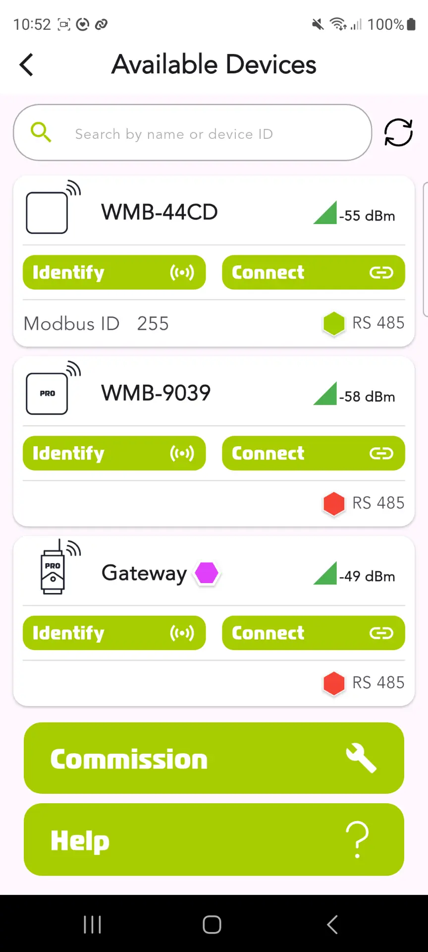




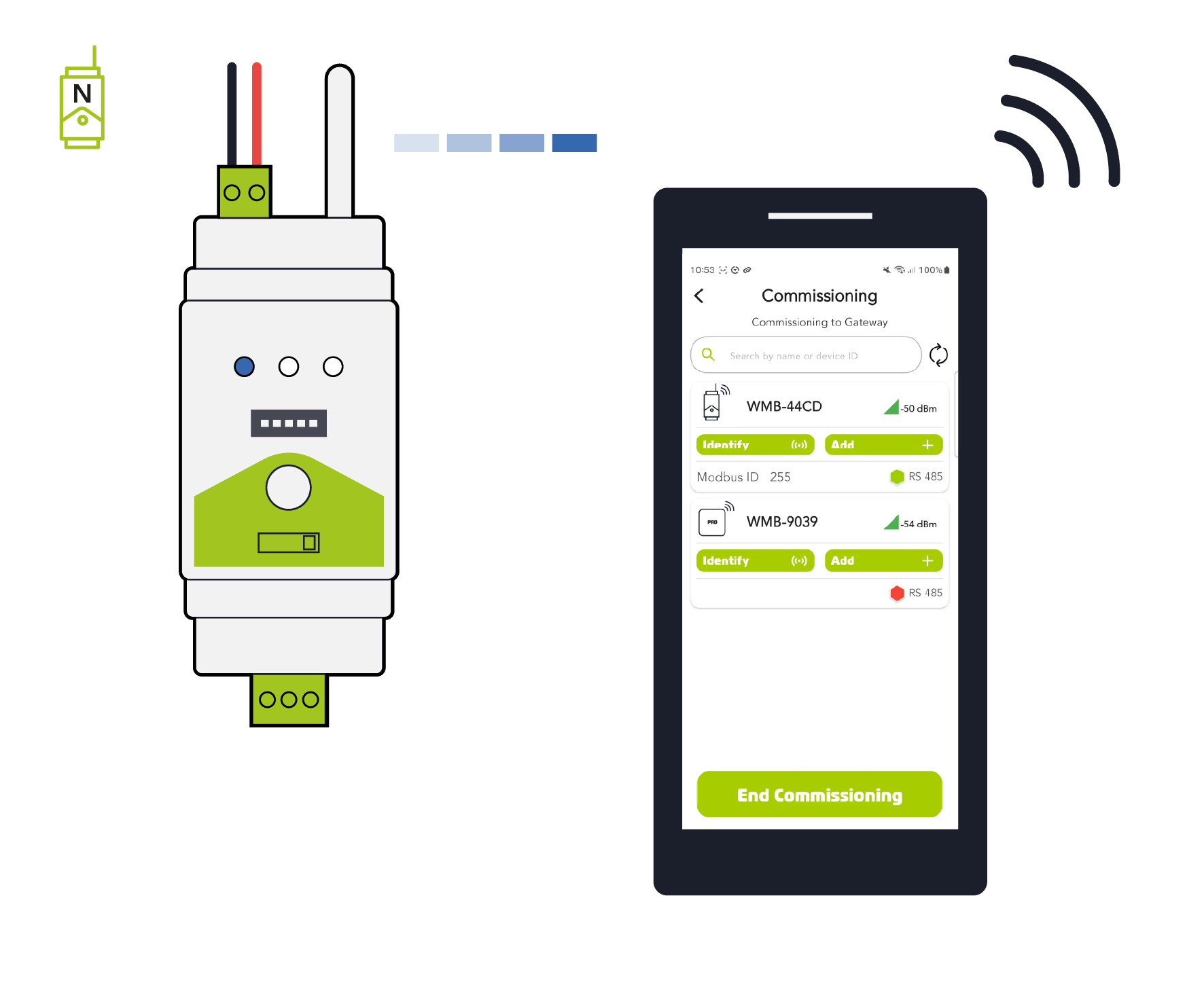
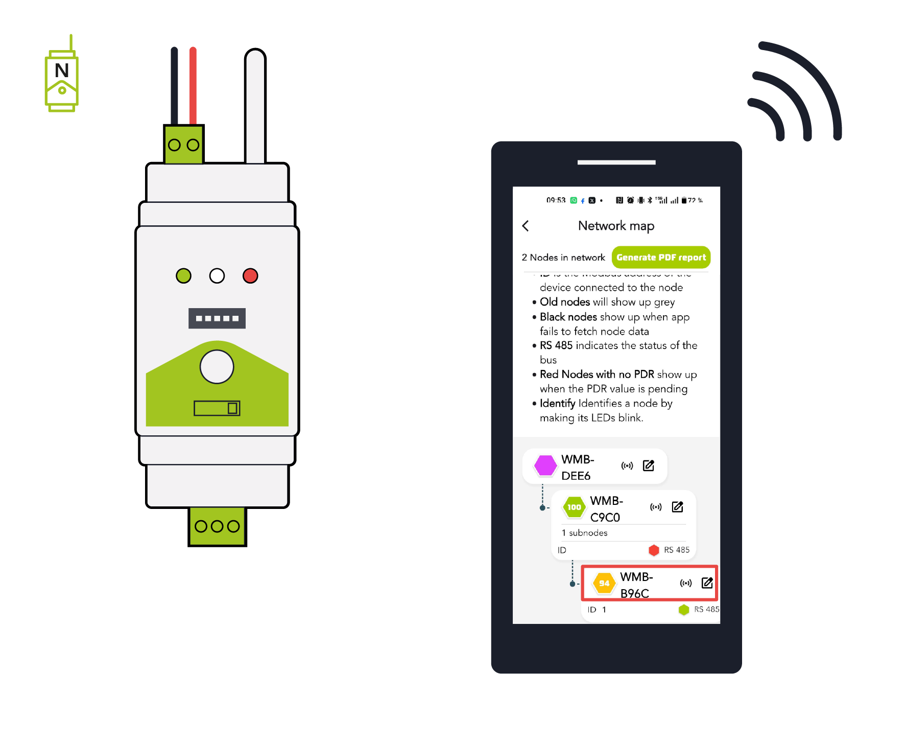
 will cause the device to blink all LEDs white as confirmation. When you have identified the device, press the button to make the blinking stop.
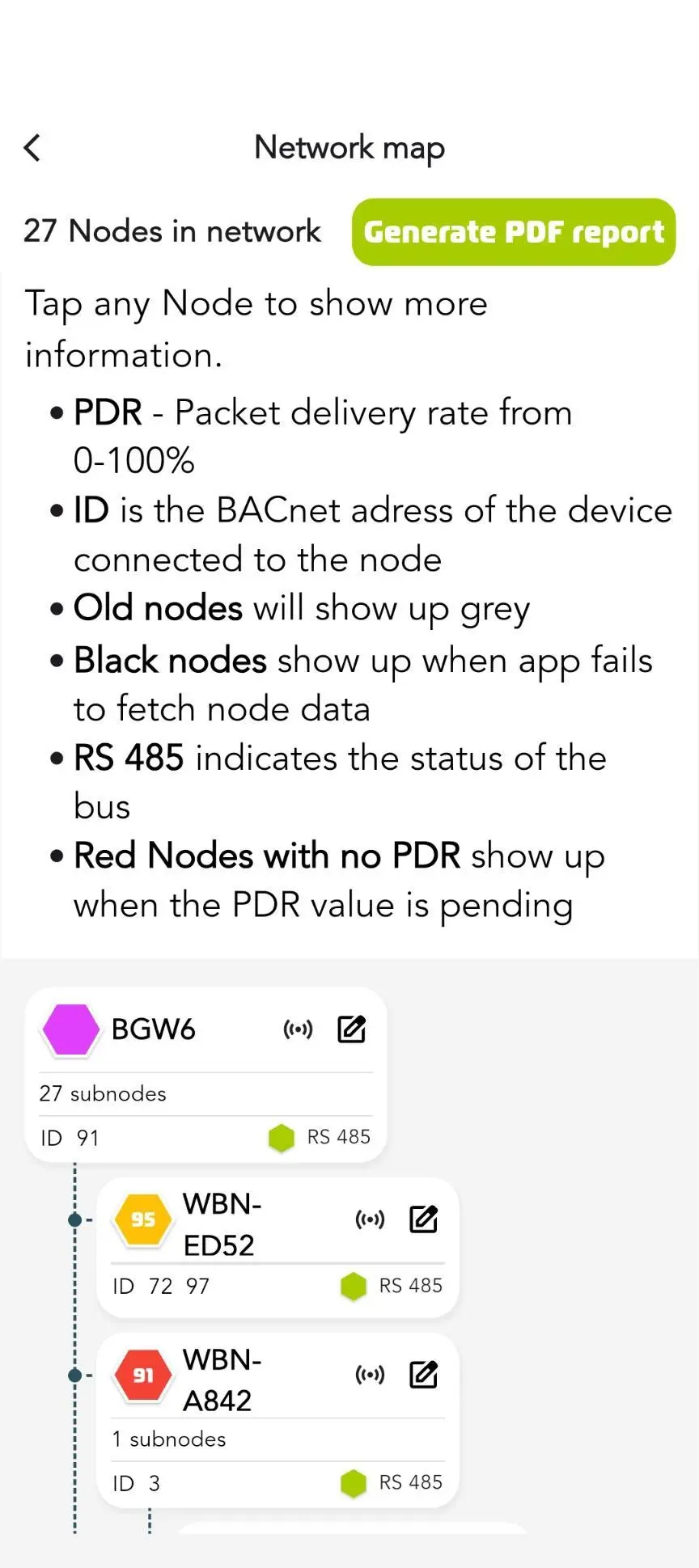
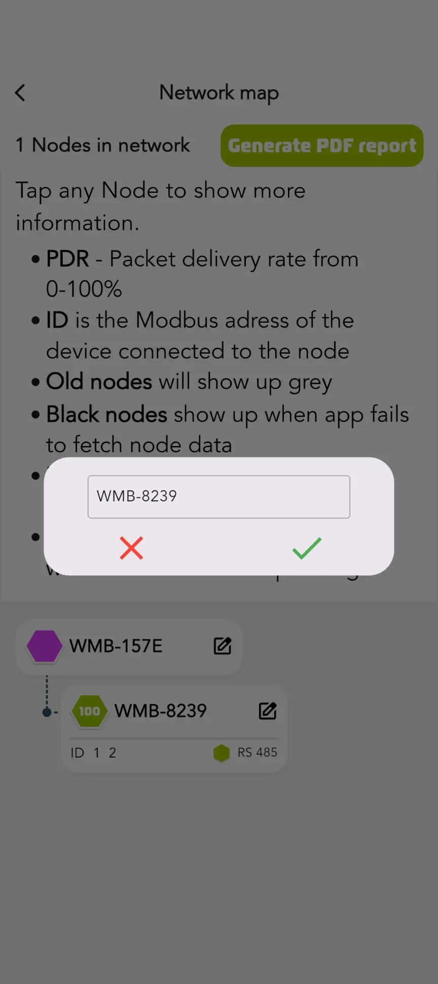
 will rename a node. See below for more details on renaming devices.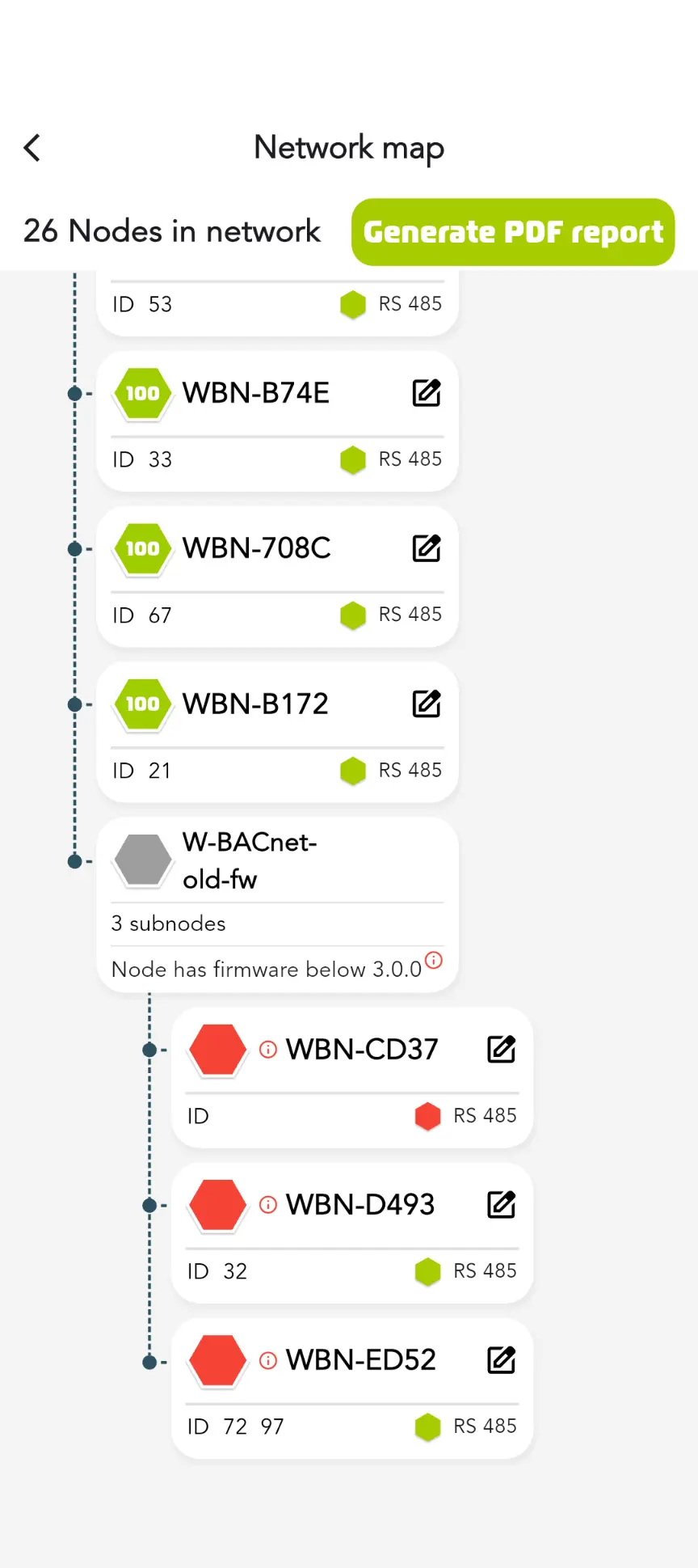





















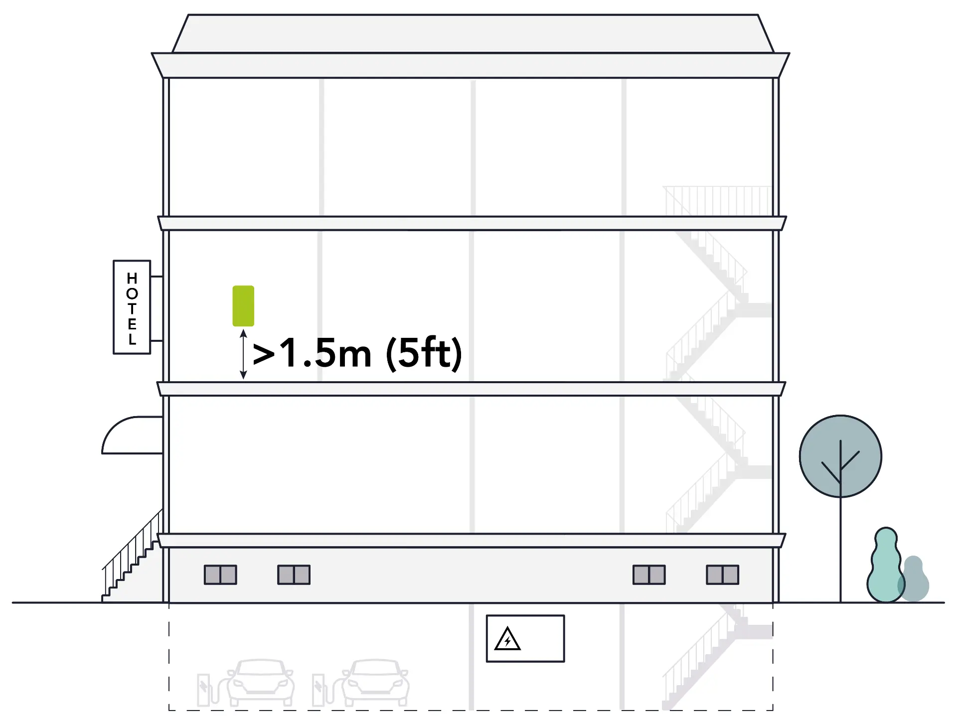
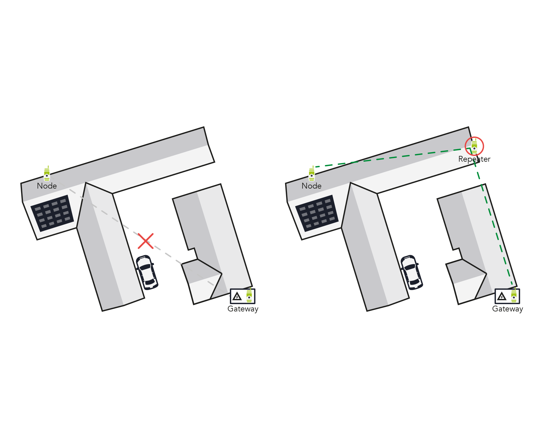
 **❌ A bad installation** does not have alternate mesh pathways
 **✅ A good installation** has good node density to allow for multiple mesh pathways
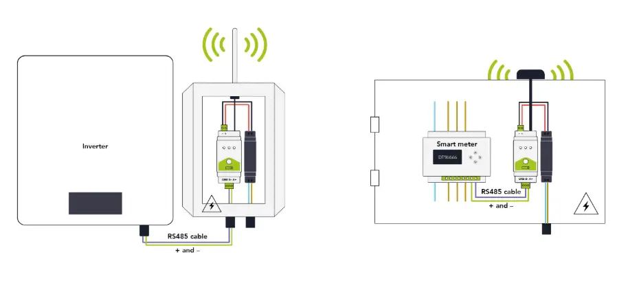

 -- 50ft/15m --